Modelling and System Design
This page discusses the modelling and system design from a technical point of view. It assumes that you are already familiar with the content of the Cluster, and in particular the issues of Integrating Historical Data. It also assumes knowledge of Unified Modelling Language, or UML. For further details on UML see the Object Management Group's UML resource page at <http://uml.org/>.
Modelling and system design was carried out using Universal Modelling Language, or UML. Four sets of UML diagram were created to help model and plan the project: a Conceptual Model, a Logical Model, Use Case Diagrams, and Collaboration Diagrams. Use Case Diagrams are discussed in the section on User Scenarios, and the other three are discussed here.
Conceptual Model
The Conceptual Model represents an Anglo-Saxon charter at a 'conceptual' or theoretical level: it is a formal way of modelling a charter and showing how its constituent parts relate to one another. It is an attempt to produce a single model for the relevant contentent in all four constituent projects. This has proven particularly challenging for several reasons, not least because the four projects model charters in different ways, and even the types of text in each project is different (see Cluster Content). Following the FRBR model, we could give the following models of a charter for each of the constitutent projects:
- ESawyer: A document (work) issued by a king at a date, with a provenance, preserved in manuscripts (items), printed in editions (manifestations), with edited texts (expressions) and a translation (expression).
- ASChart: A text (manifestation) containing clauses and people.
- PASE: A source (work) recording an event involving named agents.
- LangScape: A document (work) containing bounds (works) preserved in manuscripts (items) which have transcriptions (expression).
We could represent this as follows:
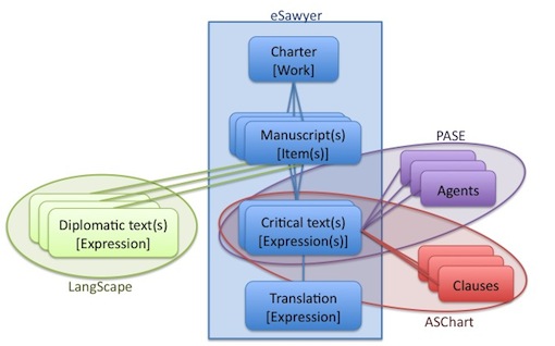
Although helpful, this model still fails to capture the complexity of data across the four projects. If we investigate further, we can draw up a formal UML Class Diagram which incorporates the material from all four projects. A more detailed model is given below. This still only includes those parts of the projects content that is deemed relevant to the Cluster, and it does not show all the properties available for each entity, only showing those which are required to unambiguously identify the entity in question. The model is as follows (click on it to see a full-sized view):
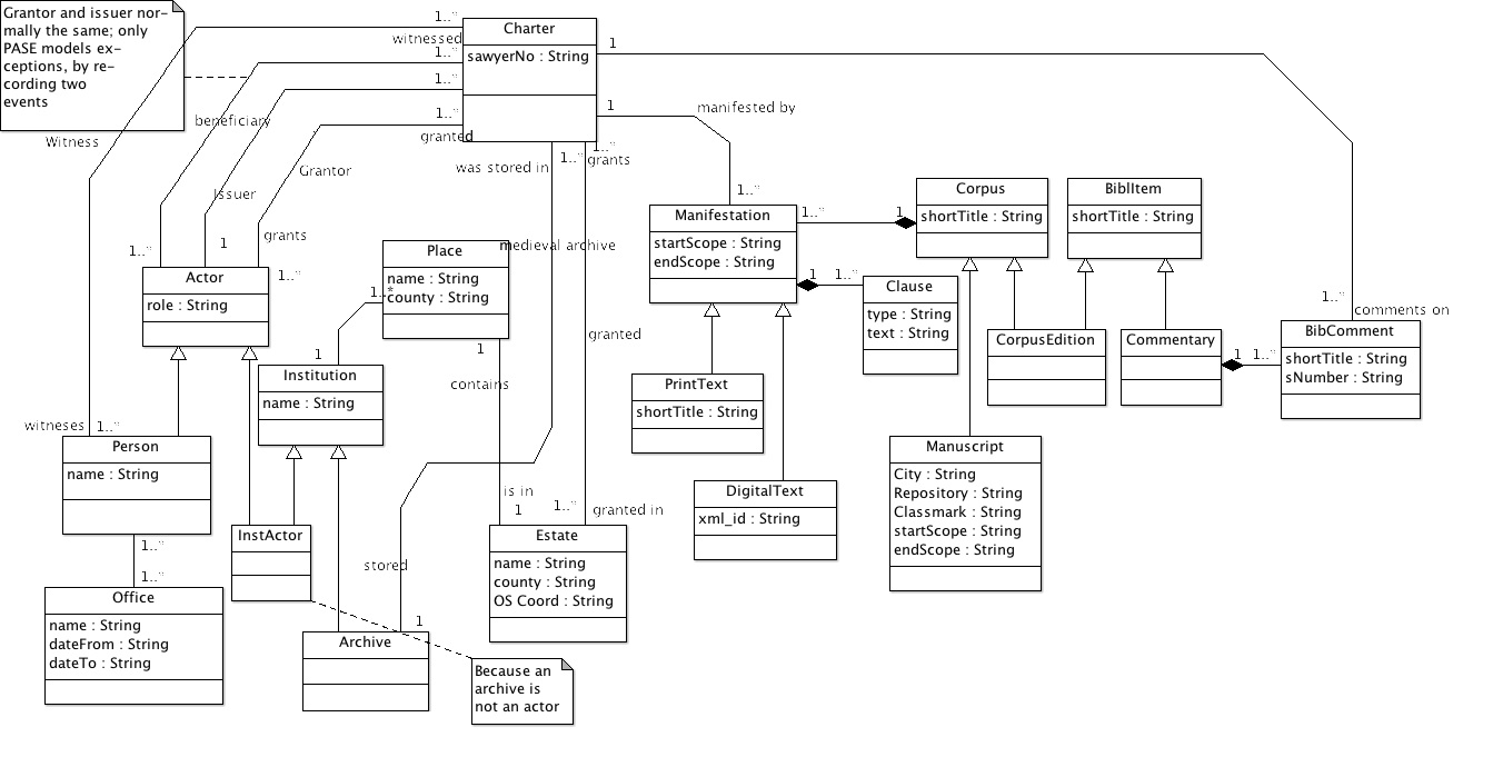
Logical Model
The Conceptual Model of the preceding section is purely abstract: it represents the content of the projects, here a charter and related entities, but does not necessarily reflect how this content will be represented in the Cluster itself. Indeed, the Conceptual Model is far too complex to use in a project with limited scope such as this one, and indeed it would require a much more complex Query Language than was used here (for which see Query Structure). For example, the Conceptual Model has many entities that are connected via other entities. One cannot ask 'which charters are in Manuscript BL Harley 2813', because according to the full Conceptual Model charters are not in manuscripts: charters have manifestations which make up corpora which are preserved in manuscripts. This complexity is necessary for very detailed queries but is overly complicated for the Cluster.
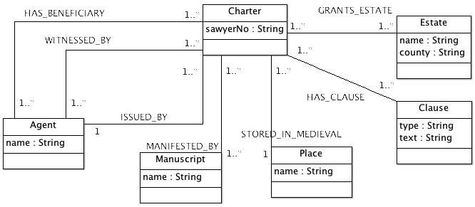
For all these reasons, a simplified and more concrete Logical Model was produced from the Conceptual Model. This Logical Model is the one that is implemented by the Cluster and the resources it communicates with in order to ensure that each project conceives of a charter in the same way. The UML Class Diagram for the Logical Model is shown below. Notice how simplified it is compared to the Conceptual Model: this admittedly limits the queries which one can ask, but such simplification is necessary in practice, and the model can easily be extended in future with very minimal changes to the Cluster itself.
TEI Schema
A further product of the Cluster project was to determine a schema for XML in a TEI Extension. This is another model of the content of the constituent projects, this time represented using an ODD ('One Document Does it all') file and following the Guidelines of the Text Encoding Initiative. This is an alternative approach to integration, as it would potentially enable interchange with other TEI-compliant projects. See further Future Possibilities.
Communication in the Cluster: Collaboration Diagrams
Part of the planning includes deciding how the components of the Cluster will communicate with one another. There were several requirements that helped to determine this:
- The constituent projects should process the queries in parallel: that is, the Cluster should send out queries to all the projects at once and then collect reponses as they come back, rather than querying one project, waiting for a response, and then querying the next.
- The Cluster needs to be easily extendible. One consequence of this is that it should be easy to add or remove constituent projects. This implies a 'star' configuration: in other words, the Cluster should be at the centre and should communicate directly with each of the other projects. An alternative arrangement would have the projects communicating with each other: although this has some advantages it would mean that every time a project was added or removed, every other project would have to adjust accordingly. This is beneficial in some cases (for example, ASChart could draw information about charters directly from eSawyer), and the possibility is built into the overall design, but the core Cluster operation should not depend upon it.
- The amount of data transmitted over the Internet should be as small as possible. On the other hand, performance is normally better if there are fewer larger transmissions than many small ones.
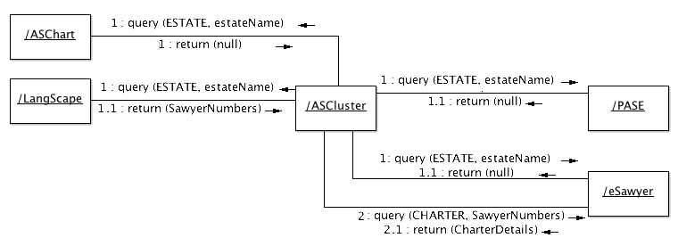
These principles (and some others, as discussed in The Query Structure) can be summarized in UML Collaboration Diagrams which show how the Cluster and constituent projects interact in order to carry out a query.
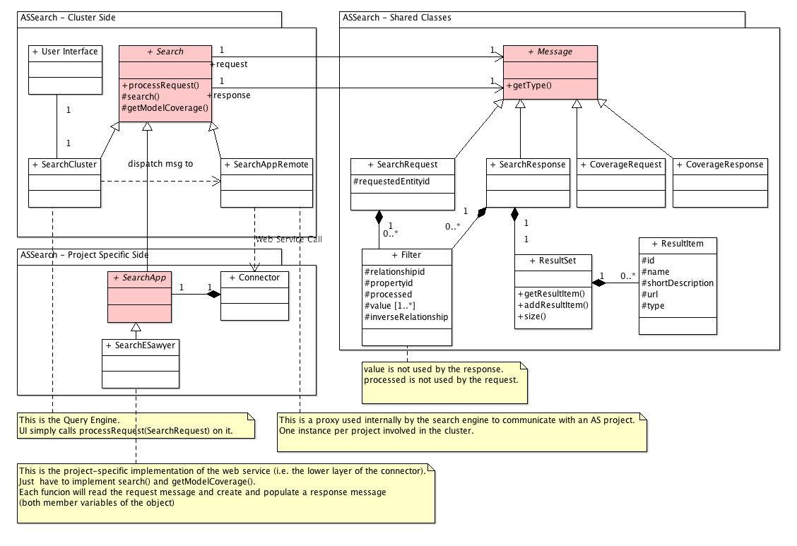
Object Model
The Conceptual and Logical Models represent the content of the Anglo-Saxon Cluster: what a charter 'is' and how it should be represented in the computer. Entirely separate from this is the design of the Cluster software itself: the architecture of the system and how it operates. The Prototype Object model then illustrates how the Cluster itself and its connectors were built: this therefore represents the software behind the cluster, not an Anglo-Saxon Charter. The details of this are discussed in System Architecture, but the design is an important part of the modelling process and so is included here (click on the image for an enlarged view).